Hey all, I wanted to share the first real use of the M3 on 5052o aluminum. I want to share because I would like feedback of lessons learned so that I can pass this on to the students as we try to improve learning how to CNC.
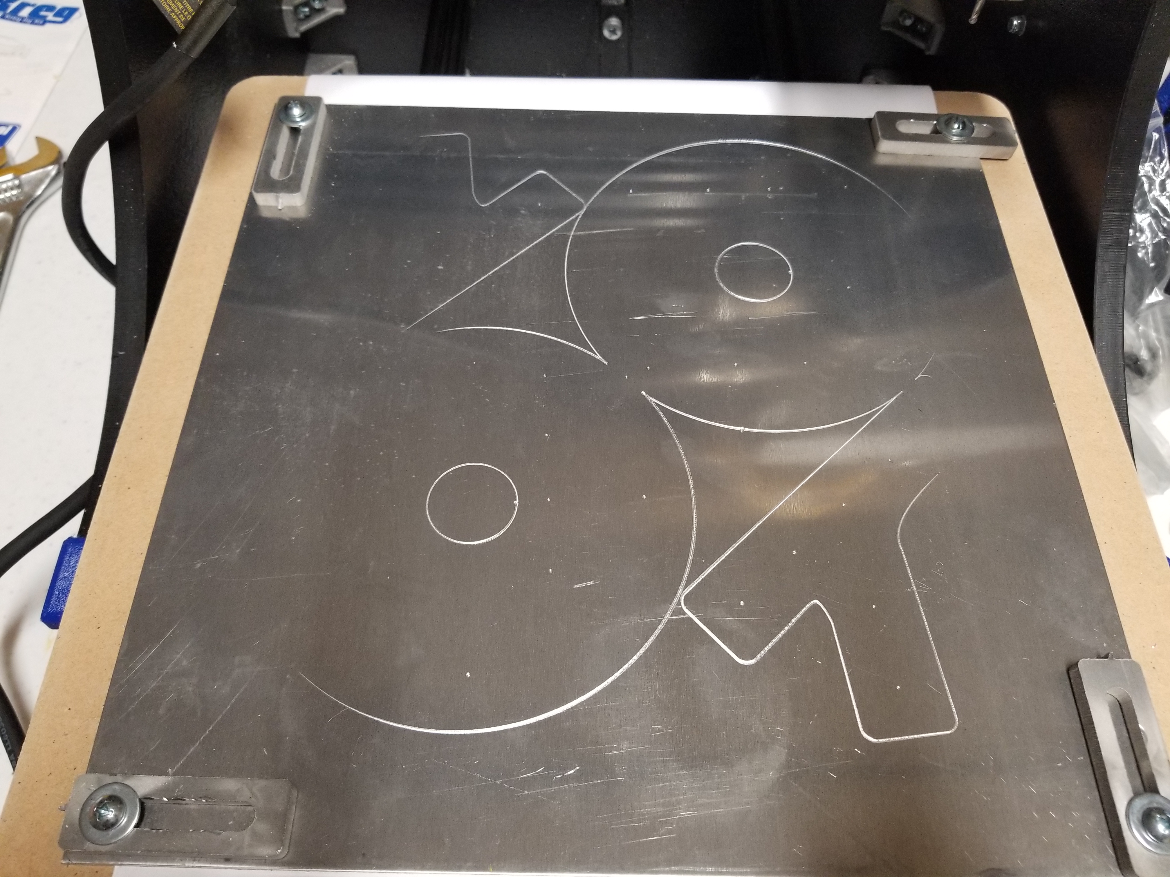
Here are the parts:
So these will go to the bogie which is now at its 4th revision
The first thing I did was that I used a marker because I wanted to confirm the gcode and that I could use the full range. I probably will not do that anymore, but it was good that I did this time around, because it made me learn to be more aware of where my zero position was. After that I tried to drill the holes... well actually to a bore operation to make the holes .164" ... I thought if I used a 1/8" ball it would do this, boy was I wrong. If you look closely some of the holes have big craters. So I tried this same technique again with a 1/16" end mill... it somewhat worked but very shallow, and then I broke the bit. So then I decided to use an actual .125" (or closest approximate) drill bit from my drill, and let the CNC gcode align the drill and I manually jog down 1/2 mm at a time. Painfully slow but effective... I concluded to use this drill bit and tap the holes only so far and then use a drill press later that works so well.
Now then the contour cuts... luckily I had a good base line from the calculator here especially for the depth, but what actually worked was using 10% override from that speed... 20% on some and 30% when it sounded quite. This took all day to complete. I'm not sure if I was too conservative... I may have gone faster, but after breaking the first bit I wasn't sure how much stress the bits can take... I just listened to the sound of the cut and went with my gut on what speed to do. The whole time doing this I used a vacuum to clean chips... (There is an awesome dust cap on another thread I saw... I think I may look into that). For the most part the contour went well... a bit slow but I'll work on that a bit more. It was fine until the last pass... and this happened:
You see on the left side there is a slight layer left, so I wanted one more pass to go a 1 mm under the bottom height, when I did this the drill bumped into one of the parts and it flew up. Luckily there were some false tabs which kept them from getting worse, but overall not enough tabs. Next time I will make sure to use enough tabs to avoid this... hence I have some software to write, because I really like HSM express and Solidworks, and the code I'm writing now works on the GCode itself... it works assuming one has access to a gcode viewer that has a backplot feature.
There is one other thing worth mentioning, one of the things we'll need to do as a team is to turn out parts quickly when the season starts next year. We only get 6 weeks, we are a custom to using adhesive on a 2D print and using a band saw to cut the parts, but this falls short on precision when it comes to drilling holes. So one thing I'm thinking is that I can edge the contour (see how I etch the fold marks I simply used the 1/8 ball down only 0.01"... etch works great and fast). If I etch the contour and tap the drill holes I should be able to turn out a lot of parts in minutes, and they should have the benefit of CNC precision, with a good turn around time. Anyhow these are just some thoughts about that... we'll have to see how things work out when the time comes.
Oh one more thing... the curivator project is *here*
That thing looks incredible! Amazing work! I've thought about etching to enable folding aluminum into 3D forms with high accuracy, but it's just been a random idea looking for a useful application. Etching hole centers, then doing the drilling with a press (and drill bits, which do a much better, faster job than router bits in aluminum...) is brilliant!
I wanted to share this pic because I wanted to continue to show the parts in action, and that the M3 did a fantastic job with precision... in particular the 1.125" holes for the bearings. Truth be known, my folding skills are somewhat lacking, but I was able work out that by use of wooden vices and using allen wrenches as leverage while I aligned the holes.
Also I want to share this to highlight a point I read in the blog about 3D printing vs. CNC. In particular the part where they shouldn't cancel out the other, since they have different strengths... amending here "that complement each other". The idea here is that 3D printing can fill in the void of 2D material, 3D printing has amazing compression strength, so this idea of sandwiching 3D printed material ensures the weakness of the aluminum bending is mitigated. while being very light with a 50% infill (using a honeycomb geometry from Simplified 3D). At one time I had the robot collapse on itself because I was experimenting with a design and since that load was tension to material that was only 3D printed... it naturally gave way. When that happened this design (calling it a bridge joint) remained intact, and the robot is at least 100 pounds load. So while other solutions use stronger materials... I'm sticking with this one, as it's light weight and affordable.
Last Edit: Sept 25, 2018 19:09:51 GMT by jamesterm
Nice work. You know we all will want to see a video of this thing in action.
You bet... me too! Today I've put on the robot its first CNC parts!
All the other parts were done the hard way with loss of precision (e.g. look at rocker bridge joint it still has paper adhesive on it)... well actually I got to a point where I was 3D printing guides to help with that, but having a CNC machine is like having a cell phone. I wonder how I got by without it.
One other thing to note about this moment, this is the 5th attempt at getting something strong enough to support the load, and so far it looks like its going to handle it just fine. So after a year or more of failure... I have to win eventually right?
The funny thing I've found... I'm including this pic since a lot of people here are into 3D printing... is that my 1/4 scale model gave some good hints as what was going to fail before it failed. It takes a bit more work to make this, but for a long-term project and for the sake of learning I wanted to give it a shot, and so now any changes go through the 1/4 scale model before making them on the robot.
We'll see... I'm going to let it set for a while to see long-term load on the parts. The key here is that deflection in the versa frame is favorable in the direction the geometry is laid out. Where my previous versions it was not. While this is being testing I'm going to build the other side, once I get that installed and the motor and chain. I'll come back here with a video!
Last Edit: Sept 26, 2018 15:36:41 GMT by jamesterm
So next is the caster wheel, and then the robot will be able to be roll again.
This render shows where the caster wheel is and its surrounding environment the battery mounting piece. Everything except the mounting section of the caster wheel already exists and in place. Note: everything that is blue is 3D printed. Most of the robot's printed parts were ABS but now some of the more critical pieces are pet-g. The strut that holds the wheel itself is already built as it is the remains from the previous inner center wheel design (that failed). One other interesting thing, there are carbon fiber rods running across the top, this helps keeps it rigid, which was necessary during the time it was suspended.
For the caster wheel I need 4 CNC parts the 2 disc pieces that mount to the lazy susan, and the 2 gussets that bind the 2x1 versa frame pieces to the strut frame.
So this etch pass was used with 1/8" ball nose bit, and is mostly successful, except that I believe my ledger paper is causing the stock to slightly bow, which explains why the ends do not have any etching. I may need to reconsider how to place the paper if I am going to use it to protect the spoiler board. The main reason for the etching is that I've had alignment issues between tool jobs, and so I want one pass to capture it all so that I can tweak the zero point. In practice I may have to shift the X and Y anywhere from 0-1mm, I'm not sure why the loss of precision but this seems to be an effective way to solve it. The second reason is to test what I'll do for FRC, and have the kids take something like this (with deeper divots, and milled inner cuts) and finish making it on the band saw.
Here is where it currently is as of today (the day of this entry)
I learned something today, looking at this if the 1/4" bit contour cut (rough pass) looks smooth it's because it's trimmed properly. If it looks rough its because the flutes are gummed up with heated aluminum. I suspect this happened because the feed is too slow, or perhaps the depth was inconsistent and plunged down too far... I can tell when this happens because the chips look chunkier. I'm still wrapping my head around this session and trying to work out how to avoid some of these issues moving forward. At one point it got so bad that the bit stopped turning it and the collet got real hot, and then it took a while to get the aluminum off the bit.
One thing that is working great though is the tabs, they provide relief when the milling starts to sound bogged down, and the one triangle piece finished all its passes as I am not worried about it popping off. It will be interesting to see what happens when I get the rough pass finished, and start to use the 1/8" or 1/16" bits to mill at the tabs.
This entry (and previous) goes to all the beginners like me who are trying to mill aluminum. I saw the videos, they specify feed of around 34ipm, I get the SFM with a speed 2 on the router, and finally I stop being a chicken and let it run at 100%... here's the result:
I have finished the rough pass using the tab software. It is a simple tabbing that lifts up the z axis and sets it back down... it's not perfect but it does help relieve the chip load if something starts to bog down. Unfortunately there was a bug that caused it to drift out, but I can still use the part. I think I know what it was, and I may fix it, but it depends on what long-term Cam software I use in the future. I may switch over to Master Cam since it has tab support. In this picture the circles didn't have tabs (I knew they would be fine). The tabs on the lower triangle would have worked if I had only one completed run of the tool job (like it is for the top triangle).
Applied finish pass... Ideally it would have just been the 1/8" end mill, and in theory should have been the same feed since the speed could be increased, but it ended up being about 27 ipm. I went 3 passes down with the 1/8", and switched to 1/16" because I had some parts that were too close together (this is a lesson learned... I only want to use 1/16 for finish not to mill). 1/16" cannot get a high enough SFM (only about 441) and a feed that works is about 12 ipm, when milling. Fortunately 2 of the parts finished great and they came off easily as the tabs were cut by the finish pass. However, the other 2 parts had issue because of the lack of leveling, which I'm not sure yet how to solve. I ended up using the band saw to get those parts out. I think the problem is the spoiler board has some scars that need to be sanded down.
Next will be the drill press for the divot holes, and then assembly. Stay tuned...
After taking it to the drill press and some deburring on the sander I get this: So I test hole alignment with the 3D printed spacers, which allow room for for rivets: On the next pic below, this etching operation is critical, I have an existing part that needs to be exactly 3.8" (or slightly smaller) from the machined hole of the versa frame. Using this etching technique, I manually zero the bit to the machined hole and type in gcodes: g20 (inches) g91 (incremental) g1 y-0.375 f34 Now Y is aligned... I then use a paper to zero the Z... when it partially bites the paper I jog down 0.2mm more Turn on router to 2x speed using a ball nose 1/8" bit type g1 x2 f34 It makes a perfect etch line, when I go to band saw I can see exactly what I need to cut, I could then verify against the printed part
This pic here is something the students will appreciate, I'm showing the benefit of a CNC machine as we never have this good of alignment!! I was able to put all the rivets in without needing to hand drill for misalignment! This is so wonderful!! Sorry I got carried away, now I should add that this time around when doing a tool change I double check the zeroing each time against a hole as it may shift up to 0.5mm. I'm still working out the science behind when it does and does not. Finally the assembly is all put together, there were no precision issues at all! Next, installing on the robot
Here is a pic of it installed it took a while to align screws to above versa frame pieces, but I was able to use smaller Allen wrenches to get initial alignment then using #6 screws to fine tune it. Was then able to use the #8 screws.
I was able to roll the robot out to its new home... which is now free to roam the building... Unfortunately, the lazy Susan couldn't handle the load when trying to move backwards (where the caster wheel is rotated all the way around). So I'll need to work out how to solve this. It's ok, when something fails I really learn from it!
I just couldn't leave this project on a sad note, here is a proposed fix I'll try:
This will make use of all the work done, and solve the Lazy Susan problem, by bolting the plates together. This means the wheel is stationary which is great from a statics point of view, because the wheel will remain under the battery weight load, and has the best leverage staying there. To allow for in-place turning or sharp turns with minimal skid, Omni Wheels are great to solve this. I considered using them before but they may not do so well off road for in-place turning. That said, my goals have changed to having something that can drive around the building to show the kids that come to see it.
So today I've talked with some of the *Texas Titans team about the Omni wheel change, and explained that this is a short term solution as it will work well on flat ground but not so well on various terrain. They agree with it given the long-term solution.
I'd like to share the long term goal with you as some of you may be able to provide some advice on it when I come across it. Firstly, the caster wheel solution was a fix to overcome the failure of the differential, which exists and works, but deflects way too much due to its lack of rigidity given the load of the bucket on extreme ends. The bucket is all 3D printed and so are the linear actuators that connect to it, so the total weight is probably around 5 pounds or less on the end, but given its extended range it can generate at least 25 foot pounds of torque or more, when I get closer to solving this I can use a torque wrench to get an accurate measurement. I'll want to design a differential that can handle this amount of load with less than 3 degrees of deflection. So this will be a thing where I use a gear tooth calculator and then will most-likely work with a spiral bevel gear in a steel box. I definitely will need to have some experience with CNC machines, and will need to work with harder materials like steel or titanium. I'll want to learn how to compute this to have some prediction of what I'll need. Ideally if this can be done... you notice how the batteries are on a sliding rack? This is to balance the weight for driving configuration, by placement of where the batteries suspend. I also have the option of putting the batteries directly beneath the fulcrum (which was in the original design). Currently the batteries are in the back to give best counter balance when the arm is deployed, and this works well with the caster wheel as it relieves some of the weight from the rocker bridge joints.
*This team is a subset of some of the mentors from our BroncBotz who helped me to compete in the NASA competition.