|
|
Post by jamesterm on Aug 26, 2018 21:44:17 GMT
Hello all,
I am very new to CNC, but spent the last 4 years heavy into 3D printing (I guess you can say I'm tired of things breaking and want stronger materials haha), and I was inspired by ClarkDV's video where he moved the controller box external. Because I am new... I'd like to offer (most likely through GrabCad) a solution for beginners that is as easy as printing all the parts... for just the basic controller.
Here is the progress thus far: Where this frame will mount onto the box. 
I've searched the forum to avoid re-inventing the wheel... and there are a lot of ones out there, not sure if there is a good fit given these parameters. I'll keep looking but otherwise I'll go down this path.
|
|
|
|
Post by Bruce on Aug 26, 2018 22:05:53 GMT
If you have experience in 3D printing I would think there would be those interested in the design you have.
|
|
|
|
Post by jamesterm on Aug 28, 2018 17:55:03 GMT
Update on this project: We decided to have the fan blow the boards from the side, this with the heat sinks in the same line should be adequate. This will end up being a box with 1/8" lexan around the sides. The framing is 3D printed using pet-g. The empty space in the upper region may be used for the pause feed and stop buttons in the future. For this first iteration we'll look into some cowling geometry for the front piece, and I'm not certain yet what to do for the back. As it stands now it can work, so I may cut the lexan with the the m3 in its current state.  |
|
Bubba's Workshop
Full Member

Posts: 166
Location: Ludington, Michigan
Machine: M3
|
Post by Bubba's Workshop on Aug 30, 2018 14:48:20 GMT
OH I like that...  |
|
|
|
Post by jamesterm on Aug 31, 2018 5:19:22 GMT
I'm jumping ahead in the design to get an idea of what it will look like when it is done. I don't have the CNC shield card in this rendering as I can't find it anywhere, but no matter... The implementation is close behind. I think once I get the printing finished and assembled I'll go ahead and release the CAD... (want to ensure I didn't mess up somewhere). While I'm here... there are some other things I'll release with it: 1. An insert part that can hold a sharpee marker for initial testing 2. Feet stands on the corners, and a couple more to close the semi circle openings where the wire comes... this way if you pick it up the wires are secured. For this first iteration... it will be as you see here... I may look into having the buttons on the top in the next iteration. P.S. All the screws used in this are American sizes #4, #6 and #8... I don't really care for metric screws.  |
|
|
|
Post by jamesterm on Sept 5, 2018 23:09:25 GMT
Here is a current update... all 3D parts are finished and assembled, but still need to CNC the Lexan... Once that is done I'll release this in GrabCad. I was going to do some cowling venting geometry but instead decided to make use of a cheap window a/c filter that is 3/16" thick. I am hoping this solution is good enough even for saw dust, but this should be fine for aluminum and Lexan. On a side note... I plan to use HSM express with Solidworks as the Cam software. I am going to see about using an 1/8" bit on .125" Lexan (Poly-carbonate)... unfortunately, the Dewalt router runs at 16,000rpm minimum so that gives me an SFM of 550... a 1/16" bit could get me a lower SFM count so I may try that if needed... this is all new to me, but I want to do it correctly without having to invest in slower spindles if possible. So any advice on what SFM count should be (as well as chip load) is welcome... searching around I've seen different answers for this. I'll have to search these forums a bit more to see if there are specifics on this for the M3.  |
|
|
|
Post by Mototech on Sept 6, 2018 1:26:34 GMT
Yeah, polycarbonate likes to melt. You can get pretty high feedrates with a high speed spindle by using multiple passes with small step downs. Blowing compressed air on the bit(very carefully keeping body parts away from the bit) can help too.
Edit in: I usually cut .093" polycarbonate at about 1000mm/min with a 0.5mm step down per pass, using a 3mm end mill( lil' bit smaller than a 1/8"). Haven't messed with the spindle speed, I always run my dwp611 at full speed when cutting acrylic or polycarbonate.
|
|
|
|
Post by Bruce on Sept 6, 2018 1:34:39 GMT
Nice enclosure. Looks like it should work out great for you. What software did you use for the model rendering?
|
|
|
|
Post by jamesterm on Sept 6, 2018 2:23:35 GMT
Nice enclosure. Looks like it should work out great for you. What software did you use for the model rendering? For the model rendering I use Solidworks (currently 2017) with the photoview 360 add-in Here's an update of a similar rendering, which should be complete. The fun challenge with this was the filter... I cheated... I took a picture of the filter under good ambient lighting of the sun on the driveway, and then put this as a texture on a simple flat square geometry, and then tweaked the illumination settings on the render preview. While I'm here thanks mototech for your setup! If my math is correct your SFM is 834 with a chip load of 0.000729. So I feel a little bit at ease attempting 550. 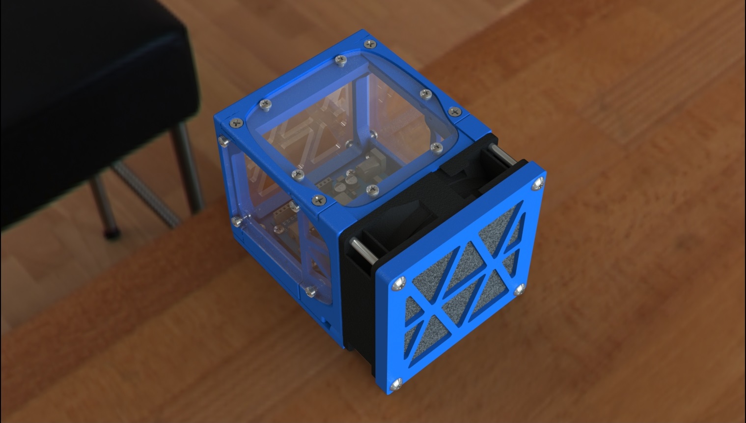 |
|
|
|
Post by jamesterm on Sept 9, 2018 4:13:36 GMT
Well it is finally finished... I'll come back and post a grabcad link, but for now here is a pic: I'll have the following shown here: 1. Cad of the controller box 2. Cad of each of the corners protectors (machine is elevated 1/8"... the connection flanges have a slight 3 degree daft to grip onto machine) 3. Wire management on semi circle openings so machine can be picked up without worry of wires falling out of notch -They can be loose now as well
4. Sharpee marker mount... great for beginners to solve some earlier tests! Thanks ClarkDV for this idea!! Stay tuned... will be back with a link.  |
|
|
|
Post by Bruce on Sept 9, 2018 14:56:29 GMT
Nice work. That fan filter should come in handy.
|
|
|
|
Post by Derek the Admin on Sept 9, 2018 17:31:01 GMT
The rendering looks excellent.
|
|
|
|
Post by jamesterm on Sept 10, 2018 4:52:32 GMT
Thanks guys for the feedback... I've published it here: grabcad.com/library/m3-cnc-controller-box-1I've included assembly instructions on there, and a STEP file for those who do not use Solidworks. Check it out feel free to ask me questions about the instructions (here or there). GrabCad will link to some other projects I've been working on. So if you happen to come across the robot I've been working on... I can't tell you how much these past 4 years I've missed using a CNC machine for it!!! |
|
|
|
Post by Derek the Admin on Sept 10, 2018 11:52:06 GMT
For some reason when I made my post it was it showed me the updated replies. The actual object looks great too. Thank you very much for sharing it.
|
|


