|
|
Post by jamesterm on Nov 29, 2018 21:46:25 GMT
Hi all as a reference (see back to curivator project in project talk for more details on this) Check out this clip: 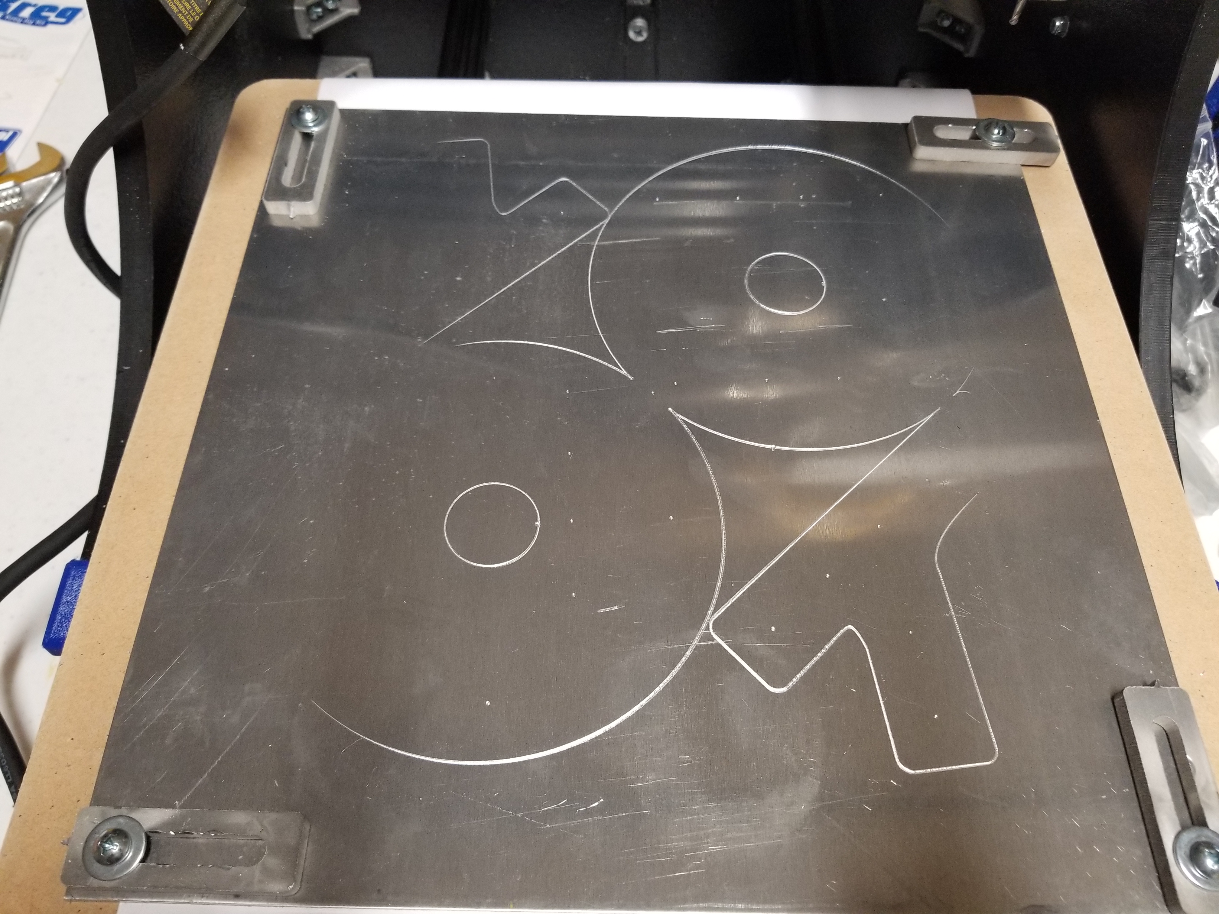 This etches the top layer and can show that the stock is somewhat bowing in the middle, what I can't show here is that it may also be not level where the right side may be higher than the left. I am not yet certain of the cause for this but I have a few theories that I'd like to share. If you have any other ideas and suggestions please let me know. 1. I have a scar in the spoiler board that needs to be re-faced 2. See if clamping like this against the paper may cause issue 3. base platform itself may not be level (may be a combination of other problems above as well) --TODO use right angle square to verify this One question I'd like to throw out there is if anyone has had problems with the base platform being level and if you have used shims before to solve problem or a better solution. Any insight on this would be helpful... Thanks. -James |
|
|
|
Post by VGCustomShop on Dec 2, 2018 13:07:32 GMT
Tramming may help you with that.
|
|
|
|
Post by Big Man Black T-Shirt(Patrick) on Dec 2, 2018 22:21:47 GMT
I had a similar issue with my M3 and I never got it completely solved. I'm sure I could have spent more time in assembly and ensured that all was square, but I was in hurry to get it running so I cut some corners. Aside from a tiny bit of onion skinning, though, it's been workable.
|
|
|
|
Post by jamesterm on Dec 3, 2018 2:04:58 GMT
I had a similar issue with my M3 and I never got it completely solved. I'm sure I could have spent more time in assembly and ensured that all was square, but I was in hurry to get it running so I cut some corners. Aside from a tiny bit of onion skinning, though, it's been workable. What is onion skinning? ----------------------------------------------------------- While I'm here... the first part of the tramming video where he put the paper under the glass is similar to what I was proposing to do. One thing I believe that can translate from the 3D printing is the idea of adjusting each corner. In the tram video he is trying to solve a different problem which brings up an interesting point: On anyone else's m3, does the router mount feel loose where it can tilt back slightly? The bolts on the X axis plates are tightened down and the amount of play appears to be the roller wheels on the V slot rail, and I know the V slot rail itself is rigid. I may come back here with a video to demonstrate. I'm not sure if it is suppose to do this, but since it seems to operate correctly I'm not sure. Back to the video... given the issue I'm mentioned above I don't have a rigid hold of the router on the Y axis, with my simple 2D cuts tramming the router shouldn't be necessary. Later, in his next video he solves the level bed issue by facing the entire support. I thought about that but the m3 can't face the entire spoiler board. So for me the take away from these video is the shim idea using a dial indicator. I have a single one but rather than doing that I can just do like I do with the 3D printer. For it we simply use a piece of paper and feel the bite of the nozzle against the paper and make that consistent on each corner. The advantage of this is that we have the proper final mounting of the router and a bit (probably the ball nose) and this should work out pretty well. I may make a video doing this and post back here. I can do this against the spoiler board itself and then do this same test on the next stock I use... once all the scars are faced off hopefully the stock itself will not need additional shims... we'll see. |
|


