insohmniac
New Member

Posts: 8
Location: Florence, OR
Machine: M3
|
Post by insohmniac on Jun 12, 2018 18:53:05 GMT
Thanks, Derek! I'll have to look at the board to see if I can find those. Maybe I can figure this out yet! If you have some photos of what I'm looking for that would be fanxtastic! And yeah, I know the software has that pause feature, but from experience with my other CNC, when something goes wrong it usually goes wrong hard and fast and by the time I get to the pause button in the software the damage is much worse than when I go straight for the hardwired stop/pause switch. At least for me, when things are going horribly wrong I somehow lose my ability to use a computer and mouse effectively, like somebody hits a pause button in my brain!  Thanks again, especially for the quick response! |
|
insohmniac
New Member
Posts: 8
Location: Florence, OR
Machine: M3
|
Post by insohmniac on Jun 13, 2018 4:18:49 GMT
So, another set of questions: I have looked at AFORWW's design from every image and the videos. I can easily design something in Vcarve to cut out for the fan and buttons, vents and wiring, but I'm hoping for a little more information. It looks like the boxes are pre-fabbed by someone, maybe just a standard open-top box from a manufacturer. I haven't found anything that shows the box with the top off, but clearly it's got extra space on the inside. Is that used for anything, or is it just for circulation? Does anyone know the dimensions? And I haven't looked closely at my electronics board today, but I'm assuming it's easy enough to add the on/off switch by connecting to a pin or set of pins? Any photos of that would be great, if anyone knows what they are looking at. If I figure this all out, I'll be more than happy to post a cut file in several formats and any links to electronics, if the moderators find that acceptable. Unless there's already a link to this stuff elsewhere on here somewhere? I guess I'll look around more... |
|
insohmniac
New Member
Posts: 8
Location: Florence, OR
Machine: M3
|
Post by insohmniac on Jun 13, 2018 18:02:05 GMT
Okay, I'm probably going to get annoying here, but I am learning all this stuff from zero, having never done anything like this before, and there's a lot to learn. I don't mind learning, and reverse engineering is how I've learned many things, but it can get expensive when you break things over and over until you finally figure it out and it works. So I'm trying to avoid that with my M3. If I need to move this post to another area, please let me know. After Derek's response to my Pause/Resume question I tried to figure it out, but I couldn't find what was referenced. So here are my questions (please see image): Now, I looked at both the Arduino Uno board and the CNC Shield board, and it looks like I use the CNC Shield board to perform the Pause/Resume functions, correct? If I'm seeing and understanding the pinouts correctly, I would connect buttons to the ABORT/E-STOP, HOLD, RESUME pins (in the lower right corner) to accomplish those functions, correct? If correct, can anyone tell me the difference between the ABORT and E-STOP options? Sometimes the damage is so bad you need to give up and Abort, and usually so bad so quickly you need to Emergency Stop, so what's the difference? Is the E-STOP just an instant stop to the machine, and ABORT lifts the Z-axis spindle then re-HOME's the unit to the Zero position (I hope my terminology is at least close here)? Thanks for any wisdom, and my apologies for how much a newb I am. But on the upside, once I know all this stuff I'll... know all this stuff!  |
|
|
|
Post by Derek the Admin on Jun 13, 2018 21:58:59 GMT
He was the one who was fabbing and modifying the boxes with the holes and what not.
The E stop isn't a true E-stop. It basically just resets the board. This will cause the router to lower because it's going to cut power to the Z motor (and the other motors) momentarily. The Abort pins are the same as hitting the stop button in UGS. It stops streaming the file and cancels any temporary work offsets that were declared with G92. What aforww was using was Hold and Resume. Hold allows you to "pause" streaming or jogging and halts motion immediately. Resume lets it continue to where it was about to go before you hit the "Hold" (pause) button. On the pic you posted, they show two pins by the hold and resume buttons (symbolized with a circle or square). If you were to wire a normally open momentary push-button switch to the pins symbolized by circles next to "Hold" then it would pause when pressed. You would wire another button the same way on the resume pins. When pressed, it would continue movement. Does that clear it up some?
|
|
insohmniac
New Member
Posts: 8
Location: Florence, OR
Machine: M3
|
Post by insohmniac on Jun 13, 2018 22:34:26 GMT
Yes, that totally helps! Thanks for that. My next electrical question is how to hardwire the On/Off switch like AFORWW did on his boxes. From what I can tell that function is done on the Arduino Uno controller, but I can't see a pin set to add the button wiring to (image below). Will the button wire to the board, or will I have to break power outside the board itself? If so, what does that require? Sorry, I know absolutely nothing about electronics, so this is well outside any knowledge I possess. If I sound stupid asking, please forgive me. But I heave to learn it somewhere, and that would be easier here than trying to track it down from yet another source. So AFORWW was 3D printing or CNC'ing the boxes himself? No wonder he didn't want to keep making them! I'm trying to identify comparative enclosure size by measuring the side of my M3 then seeing how much space appears to be taken up on AFORWW's pics and videos of his enclosure. It's not an exact science, but once I purchase what I need (wiring, buttons, etc.) it should make it easy to see how close I am to accurate. And I can fab the enclosure. The one thing I AM good at in the CNC world is making files in Vcarve. But building a CNC and working with circuit boards is a foreign language I'm trying to learn from scratch here. Thanks for your help and patience with my dumb questions and my persistence, Derek! 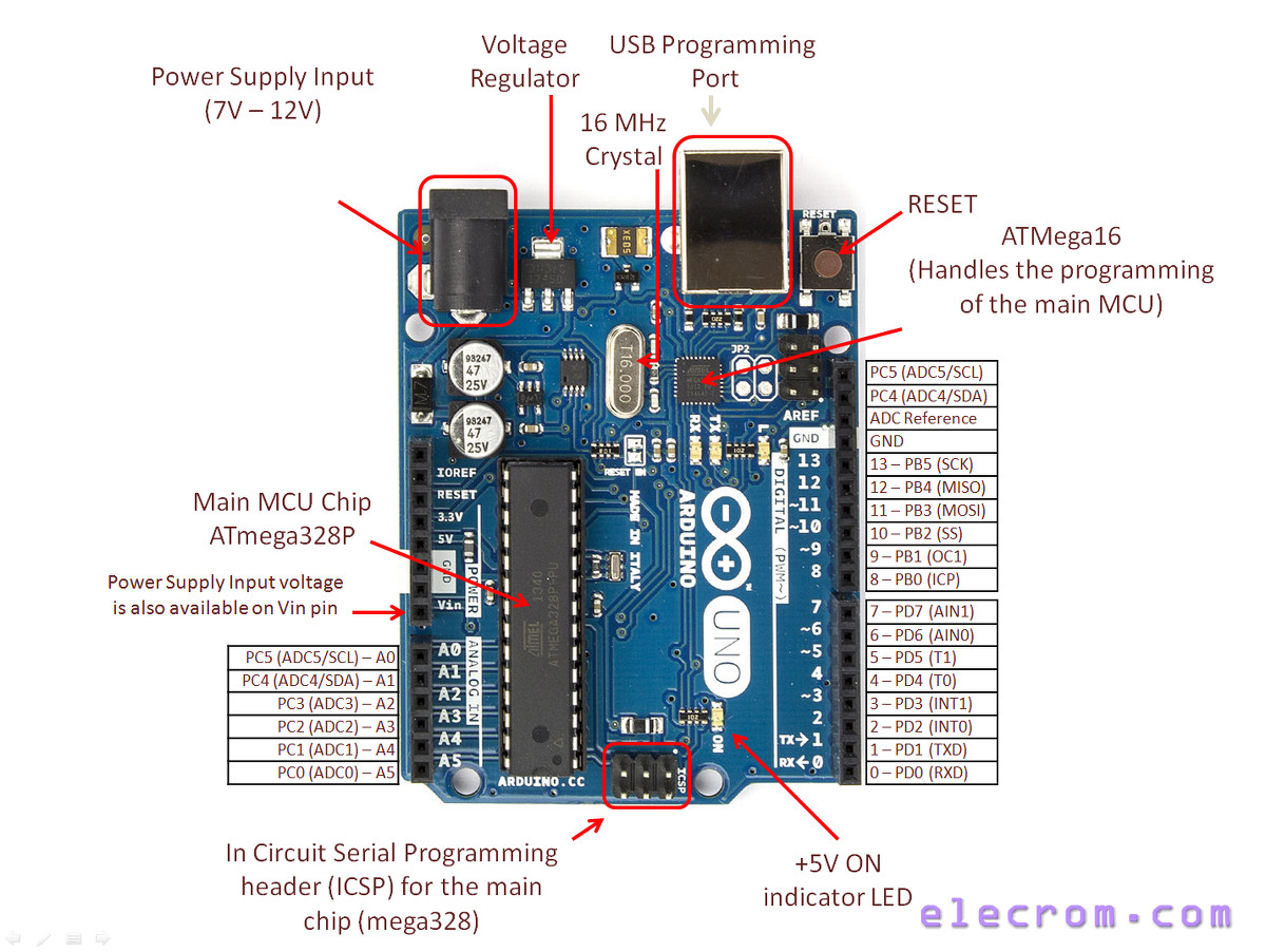 EDIT: Did some quick looking around, and came across this: Adafruit In-Line Power SwitchCan it really be that simple? If so, BAM! I'm getting closer by the minute!  Another link I looked at showed connecting an On/Off switch between the POWER GND and ANALOG IN A0 pins. Will that work, too? How do you wire to a pin plug that already has something in it (in this case one of the pins for the CNC Shield)? |
|
|
|
Post by Derek the Admin on Jun 14, 2018 12:55:50 GMT
The switch he used didn't have anything to do with the Uno because that is fed from the USB. He had a barrel plug in, then from the barrel plug to a rocker switch. Honestly I'd suggest not messing with it. Without a prior understanding of that you run the risk of blowing something.
|
|
insohmniac
New Member
Posts: 8
Location: Florence, OR
Machine: M3
|
Post by insohmniac on Jun 15, 2018 4:27:35 GMT
No worries. I may be ambitious, but I'm rational. I'm assuming if I DO blow something I can replace the electronics with one of the Arduino Uno, CNC Shield, and Stepper Driver kits on Amazon, though I'll have to throw on the OS myself, which will be it's own learning curve. I actually learned most everything I needed with many hours of online searches and research today, from wiring everything from the power (the in-line power switch I referenced at the very bottom of my last reply), to adding the Pause and Resume switches, including a touch puck in the mix, and even the NEMA box to put it all in (now I understand what you meant by AFORWW fabricating the box). There was a pretty helpful thread over in the Shapeoko forums for parts, which led me down the right search paths: www.shapeoko.com/forum/viewtopic.php?f=7&t=6662So, I think I'm good for now. I'm putting together my shopping list and questions for my "Local" electronics parts store ("Local" is 60 miles away since I live in a podunk coastal town that lacks, well, almost everything), and what I can't get there I can purchase online. Once I figure it all out and put it together I'll reply with pics, a list of parts needed, and some cut files in case anyone else wants to make it easier on themselves rather than figuring it all out on their own. But it may be a while before I get to that. I tend to load up on projects and allot myself X amount of time to do something, and adding the upgraded electronics enclosure was't part of my recent project load, so it's going to be an in-between and as-time-allows project. But once I'm done I'll brag and show it off to everyone (because I've never done anything like this before)! Thanks for all the help, Derek, and for the inspiration AFORWW! |
|
|
|
Post by Derek the Admin on Jun 15, 2018 14:40:13 GMT
Looking forward to the finished product insohmniac. Didn't want to be discouraging by the way, just cautionary. Good luck with the project and be sure to show it off!
|
|
|
|
Post by Mototech on Jun 15, 2018 21:48:33 GMT
|
|
insohmniac
New Member
Posts: 8
Location: Florence, OR
Machine: M3
|
Post by insohmniac on Jun 16, 2018 2:12:19 GMT
Thanks for the link, Mototech! That is hugely useful! I was getting ready to break out my ruler and calipers and hoping for the best. |
|
|
|
Post by jimmyk on Jun 16, 2018 16:01:07 GMT
Hey guys, thanks for all the great info. I decide to make just the Hold/Resume box since I am a newb and don;t want to crash my machine! This forum has been a great resource. Would have bought aforww, but I was late to party as usual. I will try printing out the thingiverse box for the board next.
Here is a pic of what I ended up using. Just a small plastic project box, two Momentary switches, and some wire with the little connectors already on the ends. Did the whole thing in less than a half hour for less than $15. Hope it helps inspire someone cuz it works great and gives me some assurance I can stop it quickly if I have to.
|
|
insohmniac
New Member
Posts: 8
Location: Florence, OR
Machine: M3
|
Post by insohmniac on Jun 17, 2018 17:14:23 GMT
Clean and simple. I like it! The more I consider my enclosure the bigger my project gets in my head. At this point I'm trying to talk myself out of incorporating everything into a mini ITX case and building in a 7"-10" touchscreen so I can have the the computer and the stepper controller setup all in the same place. I think I have an old NUC laying around here somewhere... |
|
|
|
Post by jimmyk on Jun 17, 2018 22:28:22 GMT
Just made a few changes...I decided to move the box up and back a bit as it was collecting a bit of dust/chips. Also, decided to add the probe port/functionality. Just added a guitar jack into the project box so I can plug and unplug the banana plug and alligator clip. Works a treat! And I can quickly disconnect to get it out of the way without worrying about shorting the connection.
|
|
|
|
Post by toomuckinfuch on Jun 20, 2018 13:56:49 GMT
Can you send g code while the machine is paused?
|
|
|
|
Post by Derek the Admin on Jun 20, 2018 16:36:36 GMT
No, you can't. It freezes commands.
|
|


